Overview of EMU Electronics System
The electronics for the CMS Endcap Muon System has two main
purposes: 1) to acquire precise muon position and timing information for
offline analysis; and 2) to generate muon trigger primitives for the Level-1
trigger system.
The Endcap Muon system uses
Cathode Strip Chambers (CSC's). Each of the
vertical chamber stations are made of 6-layer CSC's which are trapezoidal in
shape. In a CSC layer, the anode wires are in the azimuthal direction and the
cathode strips are in the radial direction. The bending of charged tracks by
the magnetic field in the endcap region is in the azimuthal direction, and the
precise measurement of the azimuthal coordinate of a hit is achieved by
interpolation of charges induced on neighboring cathode strips. The anode
wires provide precise timing measurement of a hit as well as a coarse
measurement of its radial position.
The EMU electronics system contains nine types of boards:
Cathode Front-End Board (CFEB),
Anode Front-End Board (AFEB),
Anode LCT trigger board (ALCT),
Low voltage distribution board (LVDB),
DAQ MotherBoard (DMB),
Trigger MotherBoard (TMB),
Clock and Control Board (CCB),
Detector Dependent Unit (DDU).
Data Concentration Card (DCC).
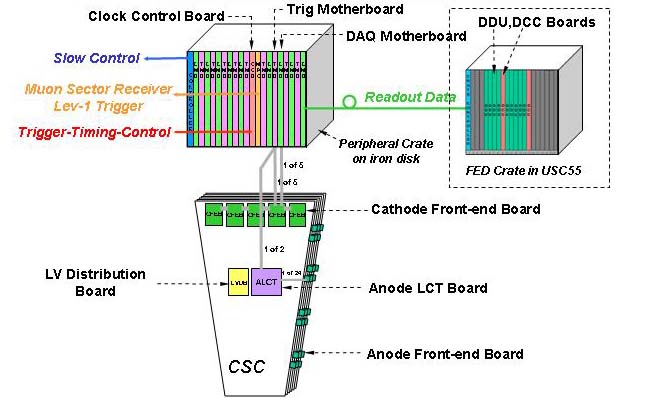
The figure below shows how the system is organized.
The CFEB is a 96-channel board and the AFEB is a 16-channel board. They are
mounted on the CSC.
Depending on chamber types, there are typically 4 to 5
CFEB's, and 12 to 42 AFEB's per chamber.
There is one DMB, TMB, ALCT each per chamber. The ALCT board is also
mounted on the chamber. The DMB, TMB are situated
in crates located on the iron disk perimeter.
The data from
the CFEB's, AFEB's and ALCT is sent by skew-clear cables to DMB, TMB boards.
The DMB and TMB serve as the DAQ and tigger interfaces to the rest of the experiment. The DMB send the readout and trigger diagnostic data to the central DAQ system
and serves as the interface for Slow Control to the front-end boards.
The TMB sends trigger primitives to the Level-1
trigger system. Timing and Control (TTC) signals are received and distributed
by the Clock and Control Board, also situated in the VME crate.
The following table shows the scope of the system.
      Chamber   No of    CFEB/chamber   AFEB/chamber   ALCT/chamber      DMB/chamber    TMB/chamber
       Type    Chambers                              288ch 384ch 672ch


       ME1/1      72            5            -         1                      1            1
       ME1/2      72            5            24              1                1            1
       ME1/3      72            4            12        1                      1            1
       ME2/1      36            5            42                    1          1            1
       ME2/2      72            5            24              1                1            1
       ME3/1      36            5            36                    1          1            1
       ME3/2      72            5            24              1                1            1
Total number of CFEB: 2088 (200,448 channels)
Total number of AFEB: 8856 (141,696 channels)
Total number of ALCT: 216(384ch), 144(288ch), 72(672ch)
Total number of LVDB: 432
Total number of DMB: 432
Total number of TMB: 432
Total number of CCB: 48
Total number of peripheral crates = 48
Total number of DDU: 36
Back to EMU Electronics Home Page