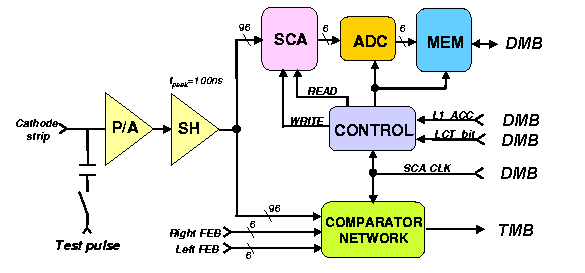
The input signals from each of the strips are sent into 16-channel
amplifier-shaper ASIC's (There are 6 such ASIC's
per FEB). Each input signal is amplified and shaped into voltage pulses. The
output pulse shape is semi-Gaussian and the shaper peaking time is 100 ns . To
minimize pile-up effects in high rate environment, circuits to cancel the long
tail of the chamber pulse due to ion drift are integrated into the shaper.
Channel-by-channel calibration will be done using a set of precisely matched
capacitors that couple a test pulse to each channel's input.One output of the shaper is connected to the trigger path whose main components is a Comparator ASIC . The comparator ASIC locates the centroids of the strip charge clusters in each chamber layer to an accuracy of half the strip width and marks its time. The resulting information is sent via cable to the TMB board where the CLCT processor look for coincidence of cluster centroids from a minimum number of chamber layers which form a ``road". The time, location and angle of the CLCT are used to determine trigger primitive parameters for the Level-1 muon trigger.
The other output of the shaper is connected to the DAQ readout path. The voltage is sampled every 50 ns and held in a Switch Capacitor Array (SCA) during the Level-1 latency. The readout of the stored samples is data-driven: they are digitized and read out only when an LCT trigger associated with the sampled pulses occurs and that the LCT is time correlated with a Level-1 Accept. This requirement significantly suppresses random background hits induced by neutrons and photons. The digitized data is sent to the DMB and transmitted to the central DAQ system.
The following table lists the number and types of IC's housed on the cathode front-end board.
        ASIC Type              No.Channels/ASIC      No.ASIC's/FEB

       Preamp-Shaper                   16                  6
       SCA                             16                  6
       Readout Control (FPGA)          96                  1
       Comparator                      16                  6
       ADC (12 bits, 20 MHz)            1                  6