 meters. The polarimeter consists of four planes of scintillator oriented
perpendicular to the incident neutron flux. A schematic view of the
detector is shown in figure
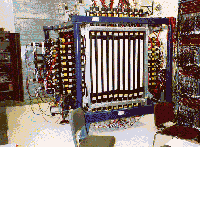
The INPOL (Indiana Neutron Polarimeter) time-of-flight detector is housed
in a small garage-like building at a flight path length of  meters. The polarimeter consists of four planes of scintillator oriented
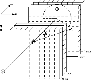
perpendicular to the incident neutron flux. A schematic view of the
detector is shown in figure
 ![]() .
.

Figure: A schematic view of the INPOL neutron time-of-flight polarimeter.
The charged particle veto paddles are not shown.
The first three planes (NA0, NA1, and NC0) are constructed out of
thin-walled stainless steel tanks filled with a BC-517s organic liquid
scintillator. Each of the tanks is subdivided into ten optically isolated
cells with the dimensions  . The
fourth plane (NA1) consists of 10 bars of BC-408 solid scintillator, each
with the same dimensions as the cells of the first three planes, and
stacked to create a fourth plane similar to the first three. The first two
planes, as a group, are the polarimeter's `analyzer' and the second two are
the `catcher'.
The liquid scintillator in the first three planes was used because it has
a high hydrogen
to carbon ratio (H:C = 1.7), and the elastic scattering of the neutrons off
the hydrogen,
  , in the scintillator is the most
efficient analyzing reaction in the scintillator.
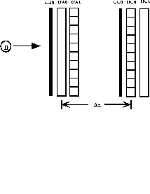
There are also two planes of thin scintillator paddles one located in front
of NA0 (CA0) and the other in front of NC0 (CC0). They are shown in figure
![]() .
.

Figure: A side view of the INPOL Neutron Polarimeter.
These paddles serve to identify, and veto, charged particles. The first
charged particle plane, taken from the upstream side, (CA0) will veto any
incoming particle which is non-neutral. This keeps charged particles
created at the target or in the flight path from contaminating the data.
The second charged particle plane (CC0) tags those events which create a
charged particle in the analyzing reaction. As mentioned above neutron
elastic scattering,  , is the preferred reaction.
The charge-exchange analog,
  , has a very small
analyzing power at forward scattering angles for the energies used in
this experiment. This means that
that reaction does a very poor job of determining the polarization of the
incident neutron, and, therefore, CC0 is used to veto those events from the
data.
Each of the cells in the neutron detection planes is viewed at each end
with an Amperex XP2262 photomultiplier tube coupled to the cell through
a lucite light guide. The timing of a ``hit'' (meaning an interaction of
the neutron with the scintillator) is determined by a mean timing between
the signals at each end of the cell. The neutron energy is determined by
the time of flight to the first two planes with respect to a corrected RF
stop signal which is derived from the cyclotron RF signal. Discrete
transitions of known Q value are used to give an absolute scale. With a
 meter flight path the typical energy resolution at
 MeV is
  keV.
keV.
The position of a `hit' in a cell is determined by the timing difference
between the signals at each end. Using this technique it is possible to
get a
position resolution of  cm along the long axis of a cell.
Therefore, overall position of a hit in the detector is determined by
knowing which cell was hit and the timing of the signals from the ends of
that cell. Once an elastically scattered neutron from the `analyzer' plane
is detected in the `catcher' plane the position information from both planes
can be used to determine the polar scattering angle,
  , and the
azimuthal scattering angle,
  (see figure
 ![]() ). The
angular distribution can then be used to determine the polarization of the
incident neutrons. This procedure will be discussed in more detail in
Chapter
). The
angular distribution can then be used to determine the polarization of the
incident neutrons. This procedure will be discussed in more detail in
Chapter ![]() .
.
Aside from the neutron-neutron events, which the detector is meant to
measure,
cosmic ray events are also collected. The cosmic events are generally
high-energy muons created by the interaction of cosmic rays with the upper
atmosphere. These events are used to calibrate the detector, and are saved
in the data stream if they fall into one of two categories: COSMIC or PP.
The COSMIC events are those which traverse and are detected in all 10
detector cells in one of the four planes as shown in figure ![]() .
.

Figure: Illustration of a cosmic event in the NA0 plane (third plane). A
hit in all 10 cells is required to define a COSMIC event.
The track created by the ten
hits is fit to a straight line and used to calibrate the position offsets
for those cells. The PP event, so-called because it fires both charged
particle veto paddles, is one which has one hit in each of the
six different planes: CA0, NA0, NA1, CC0, NC0, and NC1. These are
generally also caused by cosmic rays and, given the assumption that the
cosmic rays are moving at approximately the speed of light, are used to
calibrate the distance between the different planes. More details on these
calibration techniques will be given in Chapter ![]() .
.
For more information on the general design considerations of this type of neutron time-of-flight polarimeter see [Tad85]. For information on this detector's design and performance while in use at LAMPF see [Cis89], [Pro91], [Mer93], and [Che93]. For information on its implementation at IUCF see [Pal95].