The CFEB test setup was migrated from CFEB production test setup. The major difference is that the production test used a prototype DAQMB, while this setup uses a production DAQMB. On the software side, this test setup is based on cfeb_control software package, which shares the same library as the DAQMB test setup.
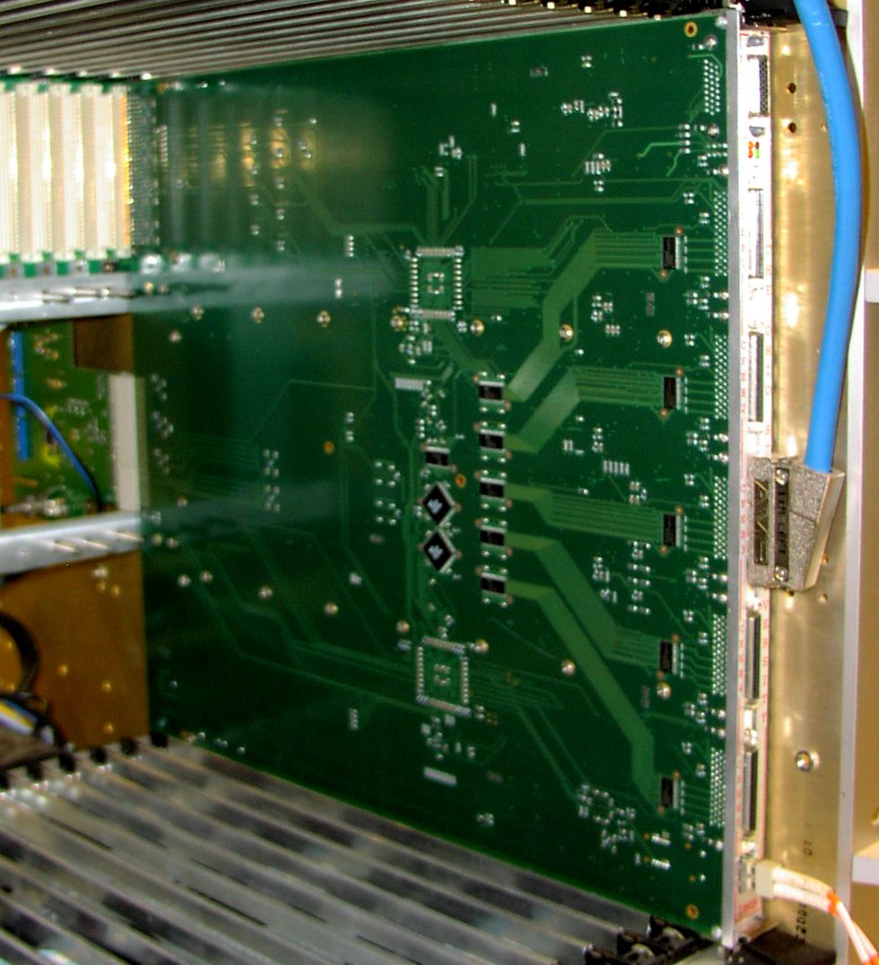
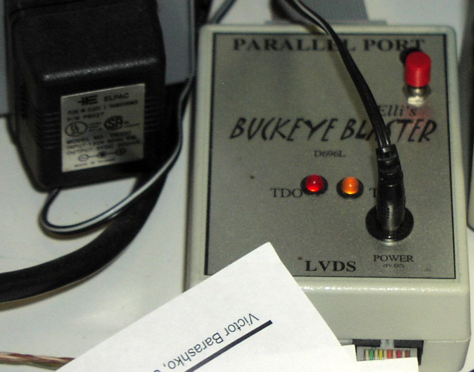
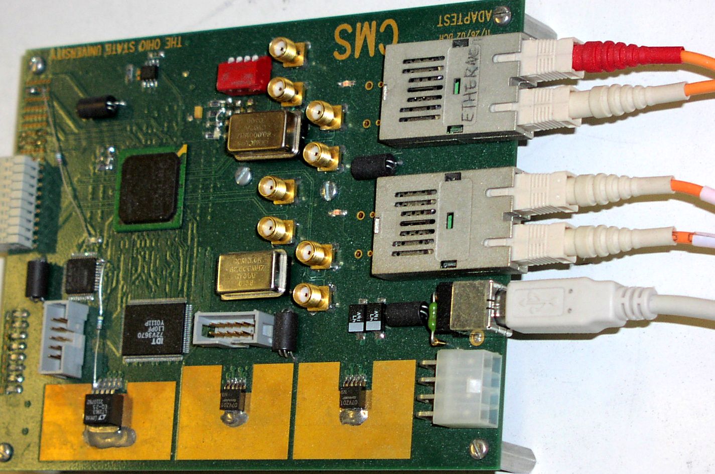
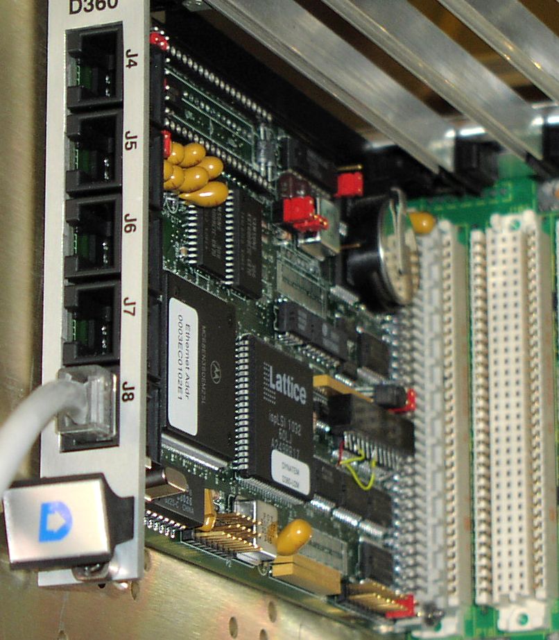
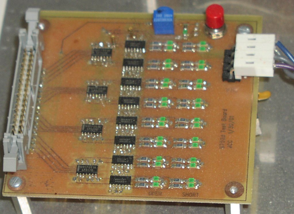
The Hardware includes: (1) one three-channel power supply; (2) one Power distribution board; (3) one CFEB under test; (4) one Comparator readout board; (5) one production DAQMB, rev7; (6) two parallel to JTAG converter boxes; (7) one DAQMB data to fiber Ethernet package converter board; (8) one VME crate with Dynatem as controller; (9) CFEB input protection diode detection board; (10) fake peripheral crate backplane; (11) computer.
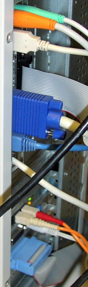
This is the diagram of the connections.
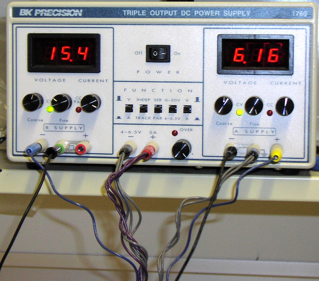
The power supply: +15V, -15V and +6.5V. Be careful about the ground connections (common points) on the power supply.
The cable connections are all drawn in the diagram. The DAQMB is in slot 21, and the Dynatem VME controller is in slot#1 of the VME crate, which equipped with VME64x P1 backplane.
The software (includes the /root and /home/cmsdmb6 ) is running on cmspc01 computer under linux with username: cmsdmb6. Here is the process to start the CFEB test program.
(1) login cmsdmb6, with usual password;
(2) open a terminal, and su (set as superuser);
(3) load drivers by "./setup_fast_daq";
(4) quit the superuser, then "cd bin";
(5) start the CFEB test program by "Cfeb";
(6) Enter your initial, then start the testing by entering the CFEB serial number first